A hybrid power plant for thermal power production is presented in figure 1.
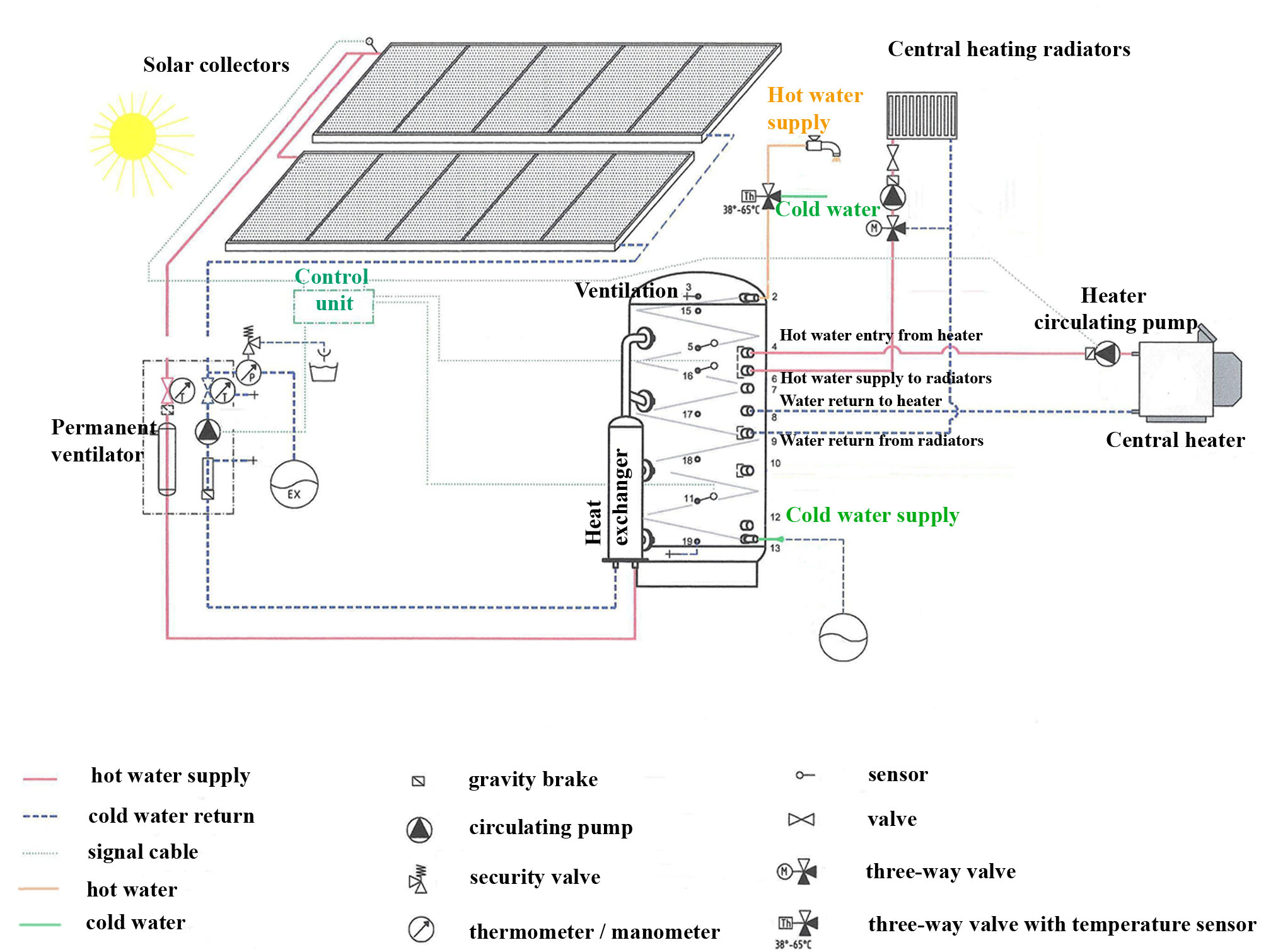
Figure 1: Connection diagram of a thermal hybrid power plant.
The above presented hybrid power plant aims to the cover of the energy consumption for the heating of interior spaces and consists of the following components:
The central control unit executes the following operations to determine the power plant’s operation mode. Specifically, the following magnitudes are measured and the corresponding actions are performed:
If the temperature Τc,o is higher than any one of the temperatures Τs,j, then the produced thermal energy from the solar collectors is stored in the water tank level with the highest temperature that remains lower than Τc,o. It must be noted that the temperature Τc,o is not measured directly after the solar collectors, but just before the heat exchanger of the water tank. In this way, the heat losses during the transfer of the fluid from the collectors to the storage tank are taken into account.
The requirement for thermal power production can be declared with two alternatives:
- either through the existing temperature of the conditioned space, in case of automatic operation of the heating system with a room’s temperature sensor
- or through the operation of the pump for the circulation of the heating fluid in the heating radiators’ network, in case of manual operation of the heating system.
In case that a demand for thermal power production is declared with either of the above two ways and the maximum temperature Τs,1 in the upper level of the storage tank is lower than the minimum temperature Τd,min required for the operation of the heating radiators, then the back-up heating unit is turned to provide the required thermal power in the upper levels of the storage tank.
The above described operating algorithm of the heating system is presented graphically in figure 2.
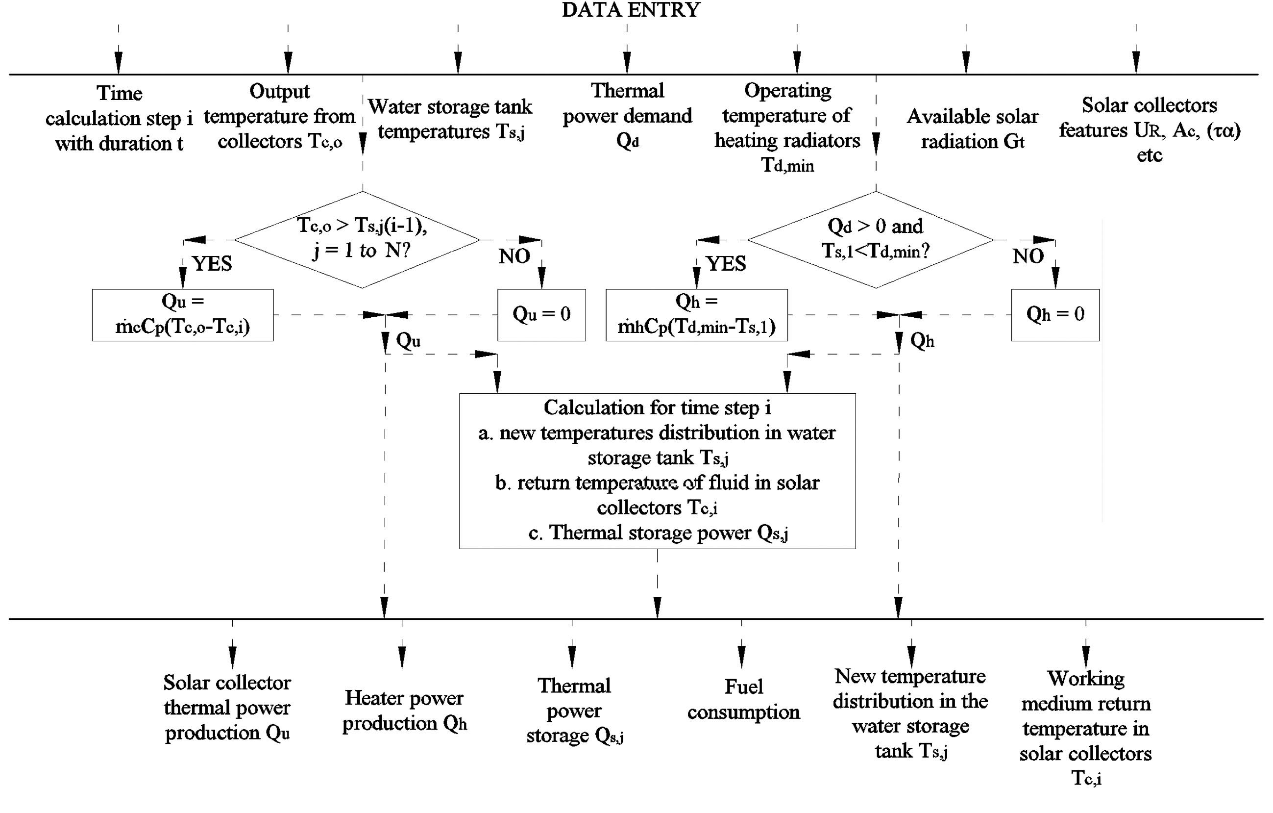
Figure 2: Operating algorithm of a thermal hybrid power plant.
In thermal power plants of large size, such as thermal power plants for heating of buildings, the required thermal storage capacity of the water tanks most probably will exceed the maximum capacity of the commercially available water tanks. In this case, in order to meet the dimensioning of the hybrid power plant, more than one water tanks must be installed. The installation of more than one thermal storage tanks increase the complexity of the hybrid power plants, regarding both the required connections of the tanks and the operating algorithm of the thermal plant.
The operation of a thermal hybrid power plant will be explained with the assistance of an example. In figure 1, a thermal power plant with three thermal storage tanks is presented.
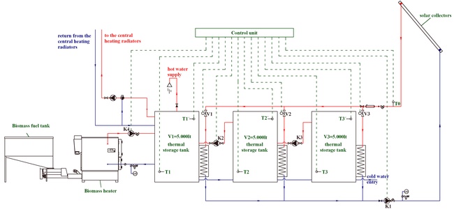
Figure 3: Connection and automatic operation of a thermal power plant with three thermal storage tanks is presented.
In this figure it is observed that the three thermal storage tanks are connected serially to each other and parallel with solar collectors. The serial connection of the thermal storage tanks implies that water and thermal energy can be transferred between the water tanks. The parallel connection between the thermal storage tanks and the solar collectors implies that thermal energy can be stored from the solar collectors to anyone of the thermal storage tanks, without affecting the existing situation in the other tanks. Thermal energy is transferred from the solar collectors to the storage tanks through closed hydraulic loops with the support of the circulating pump Κ1.
The central heater is connected exclusively with the first thermal tank, which constitutes the thermal peak tank. All the thermal energy consumptions, namely both the hydraulic network to the central heating radiators for the heating of the building and the network of the hot water supply, are supplied from this thermal peak tank. Thermal energy is transferred from the heater to the thermal peak tank through a closed hydraulic loop with the support of the circulating pump Κ4.
The thermal flow is also possible from the 3rd to the 2nd tank and from the 2nd to the 1st tank with the support of the circulating pumps Κ3 and Κ2 respectively.
The operation of the thermal hybrid power plant is controlled and supervised by a central control unit. The thermal energy storage algorithm from the solar collectors to the tanks should aim to:
Both the above targets are approached by ensuring an increasing temperature of the working medium in the storage tanks from the third to the first tank. This is achieved with the appropriate installation of circulating pumps and electro valves in the hydraulic network, operating automatically according to the orders delivered by the central control unit. However, before the orders delivery, the control unit should accept temperature signals from specific points of the heating systems, which will determine the operating mode of the power plant. Specifically, the data input for the control unit are the following:
The control unit provides orders towards the following devices:
The thermal storage algorithm practically aims to determine in which water tank the thermal energy from the solar collectors will be stored and whether the central heater will operate or not. The order for the operation of the central heater is given in case there is thermal power demand and the maximum temperature of the working medium in the thermal peak tank is lower than the minimum required temperature for the operation of the central heating radiators. The required check and the corresponding order are:
In order to ensure that the thermal energy storage from the solar collectors will be maximized and, simultaneously, the temperature of the working medium in the storage tanks will increase from the 3rd to the 1st tank, it must be checked if the thermal energy is possible with priority alignment to the 1st, the 2nd or the 3rd tank. Practically, if the temperature in the solar collectors output is higher than the temperature of the thermal peak tank, then the thermal energy will be stored in the first tank. If not, the same check is performed first with the 2nd and then with the 3rd tank. If the temperature everywhere in the storage tanks is higher than the temperature in the solar collectors output, then the produced thermal energy can not be stored. The storage procedure described above is performed with the following controls and the corresponding orders:
Finally, in case the thermal storage in the 2nd or the 3rd tank results to working medium temperature higher than the one in the 1st or the 2nd tank respectively, the working medium (and thermal energy) should be transferred from the 2nd to the 1st tank or from the 3rd to the 2nd tank respectively. This operation is ensured with the following controls and orders: